Citadel - Rocket Engine Test Stand
Lead designer of Gaseous methane Gaseous oxygen feed system for Mortise Rocket Engine. Designed for safe operation to provide the desired pressure and mass flow rate to the engine. It is fail safe. One of the largest difficulties that I had to overcome was designing this system to be GOx compatible at a low price. I reviewed the system with industry contacts.
|
|
I am the project lead for Citadel, a 1500 lbf rocket engine test stand. I am also the lead designer of the gaseous methane-gaseous oxygen fluids system to support engine testing. I am specifically responsible for the main propellant lines. I used my knowledge of compressible flow to design a system that provides the correct pressure and mass flow rate to any engine that is connected to Citadel. I did in-depth research into the requirements for a GOx system, heavily referencing NASA’s “Safety Standard for Oxygen and Oxygen Systems.” I then implemented all necessary safety requirements into my system, including compatibility of parts, ignition sources, types of valves to avoid, cleaning procedure for parts, and ConOps to ensure safe functionality while still allowing the system to function effectively. I had this system reviewed by a number of industry contacts, including Boston University alumni Doug Lescarbou, a propulsion engineer at Blue Origin.
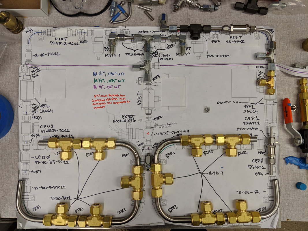
The system consists of a fuel line and an oxygen line, each with a dedicated purge system. I wrote code in MATLAB to calculate the pressure decay of the compressed gas cylinders throughout a test. The code allows for the decay to be calculated with different gases and different mass flow rates. If the mass flow rate is not known, the code calculates that using the minimum orifice diameter in the system, and then calculates pressure decay. I used this to decide that the use of 5 K-size gas cylinders would be ideal for a 30 second test of the gas-gas engine I also designed. At 5 cylinders the pressure decay is only 124 psi. Adding more cylinders gives marginal benefit with a relatively high complexity and monetary cost. It is critical to have a low pressure drop, and to know what that pressure drop is, for consistent analysis of engine performance. In the physical system, this pressure is monitored on the high side of the main regulator. The regulator has low droop, so a slight variation in the back pressure should lead to minimal changes on the output side. The system regulates pressure and mass flow rate in two stages. First with the aforementioned single stage regulator. This drops the pressure from out of the cylinders, 2200 for GOx and 2000 for CH4, to around 900 psi (for 400 psi chamber pressure). Then, flow chokes at orifices right before the engine. This allows for the control of both mass flow rate and pressure of the engine. I am using SolidWorks to lay out all of the components in CAD and route the proper tubes. I have deeply considered the layout to ensure it has the lowest pressure drop, fewest amount of components, and most economical profile, while still performing as needed.